

The current web calculator allows one to obtain the residual spectral fluence or residual energy of isotropically distributed protons and ions traversing a spherical shield by exploiting the collision electronic stopping power (based on a fit of the tables - based on ICRU Report 37 - from ESTAR code at NIST) and the radiative stopping powers (those evaluated in ESTAR - e.g., see webpage). The fitting function is a polynomial of degree 15 and the tables are reproduced with a maximum discrepancy < 1%.
In ESTAR webpage at NIST, the uncertanties regarding the collision and radiative stopping power are discussed as reported in the following. The uncertainties of the calculated collision stopping powers for electrons are estimated (ICRU, 1984) to be 1 % to 2 % above 100 keV, 2 % to 3 % (in low-Z materials) and 5 % to 10 % (in high-Z materials) between 100 keV and 10 keV. The increasing uncertainties at low energies are due to the lack of shell corrections which are required when the velocity of the incident electron is no longer large compared to the velocities of the atomic electrons, especially those in the inner shells. Because of this limitation, tabulations of collision stopping powers are customarily restricted to energies above 10 keV. A similar restriction is recommended in regard to the use of the ESTAR. Due to the omission of shell corrections, the stopping powers from ESTAR are expected to be too large at very low energies. It is estimated that for materials of low atomic number, such as water, air or plastics, the error will be to the order of 10 % at 1 keV. ESTAR will not run below 1 keV. Radiative stopping powers are evaluated in ESTAR with a combination of theoretical bremsstrahlung cross sections described by Seltzer and Berger (1985). Analytical formulas (using a high-energy approximation) are used above 50 MeV, and accurate numerical results of Pratt et al. (1977) below 2 MeV. Cross sections in the intermediate energy region from 2 MeV to 50 MeV are obtained by interpolation, a procedure whose accuracy was confirmed by more detailed calculations for a few cases. The uncertainties of the radiative stopping powers are estimated to be 2 % above 50 MeV, 2 % to 5 % between 50 MeV and 2 MeV, and 5 % below 2 MeV.
The probabilty distribution of path lenghts in the spherical absorber is obtained by means of a GEANT4 simulation.
The following link give access to the Web Applications for the calculation of residual spectral fluences of isotropically distributed electrons traversing a spherical absorber:
How to use this Calculator for particle spectral fluences or particle energies
For an incoming particle spectral fluence or particle energy isotropically distributed, this tool allows one to calculate the residual spectral fluence or residual energy in a point at distance r from the center of the sphere, with radius R, after traversing a spherical shielding material. The thickness of the spherical absorber is t.
The input parameters and options for the tool are described below. When the input form has been completed, pressing the "CALCULATE" button will start the calculation and open the "Results" page (allow for pop-up in your browser settings). The result page will be also linked at the bottom of the calculator page.
Input Parameters:
- Input type
- Target material
- Number of steps
- Shielding geometry
- Particle spectral fluence.
Input type
In the web Calculator, using the selector at the top of th calculator panel, the user can select the calculation of the residual spectral fluence or the residual energy for incoming protons or ions.
Spectral fluence is the default option: 
User has to change selection for mono-energetic particles:
Target Material
In the section "Target Selection" it is possible to specify Single Element target material or a predefined Compound material. Fraction by weight, mean excitation energy and densities of media are available here.
Following is the maximum difference percentage between the fit and ICRU tables for single elements as a functions of the target atomic number (Z):
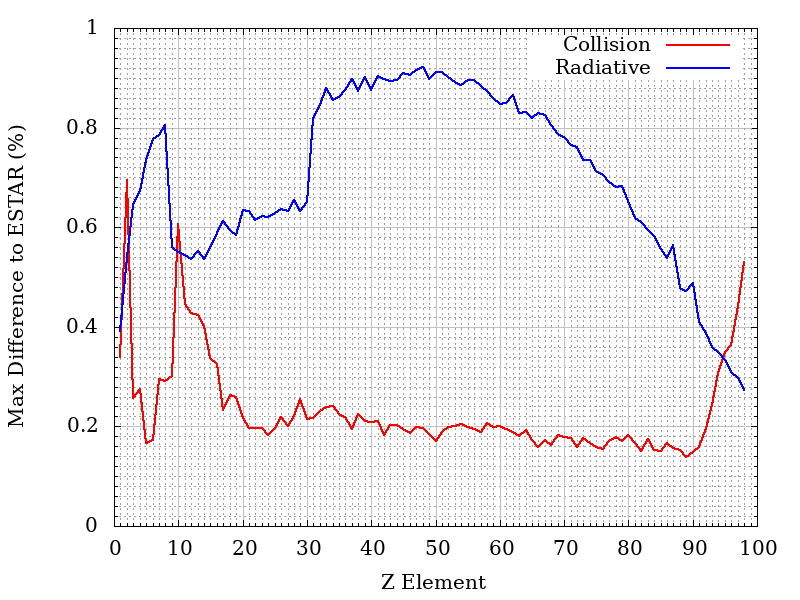
The overall max difference for compounds is 0.36% for collision, 0.91% for radiative. The average difference is 0.17% for collision and 0.73% for radiative.
Number of Steps
In the web Calculator, using the pull down menu, the user can select the number of steps of the calculation - i.e., the traversed path is divided by the number of the steps.
The results of each steps is used as input for the following one to obtain the final result for the total traversed path.
In each step, the minimum traversed path is equivalent to about 5 μm of Si (1.16x10⁻³ [g cm-2]), e.g., 0.96 cm in Dry Air at sea level with density equal to 1.20484x10⁻³ g/cm3 (as implemented in SRIM from ICRU-37 table 5.5). The number of steps will be accordingly modified to keep each step above the minimum.
Shielding geometry
In this section users can modify the external sphere radius (R), the thickness of the shield (t) and the distance from the center of the sphere (r). The lower limit of traversed path is 5 μm.
Dependence of traversed path distribution on the distance (r) from the sphere center
In the following figure, the distribution of the traversed paths inside the shielding material are shown for a) r = 0 , b) r = D/2 , c) r = 0.95 D and d) r = D, where D = R - t where D = R - t with R = 50 cm, t= 0.127 cm of Al. The ditribution were obtained assuming that particles traverse the shielding material with their flight direction unchanged.
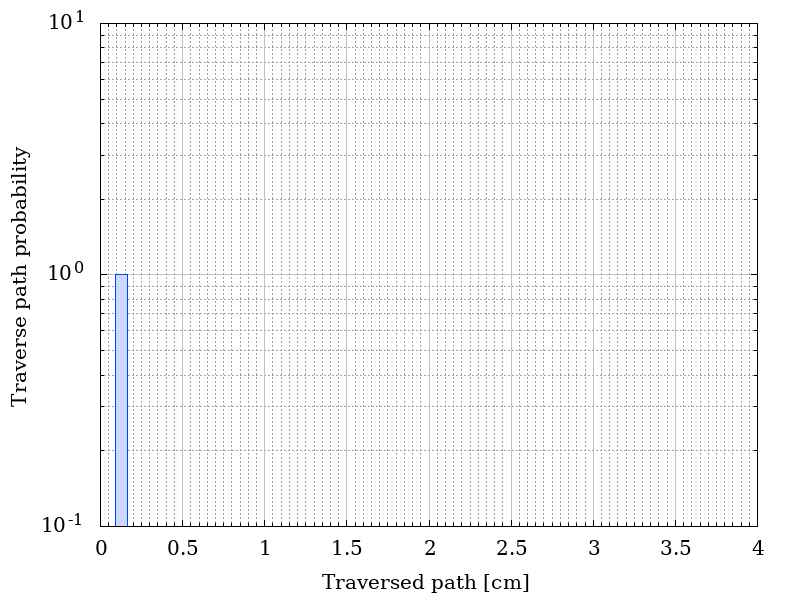

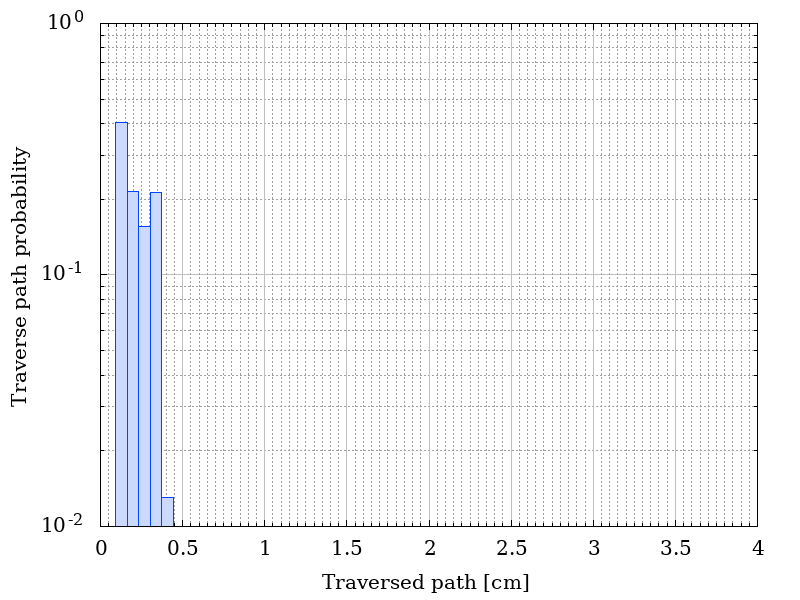
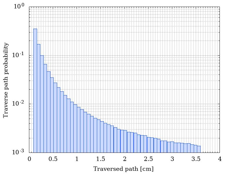
Traverse path probability as a functio of r.
The corresponding residual fluences are shown in the following figure. The incoming isotropical spectral flunece is listed here.
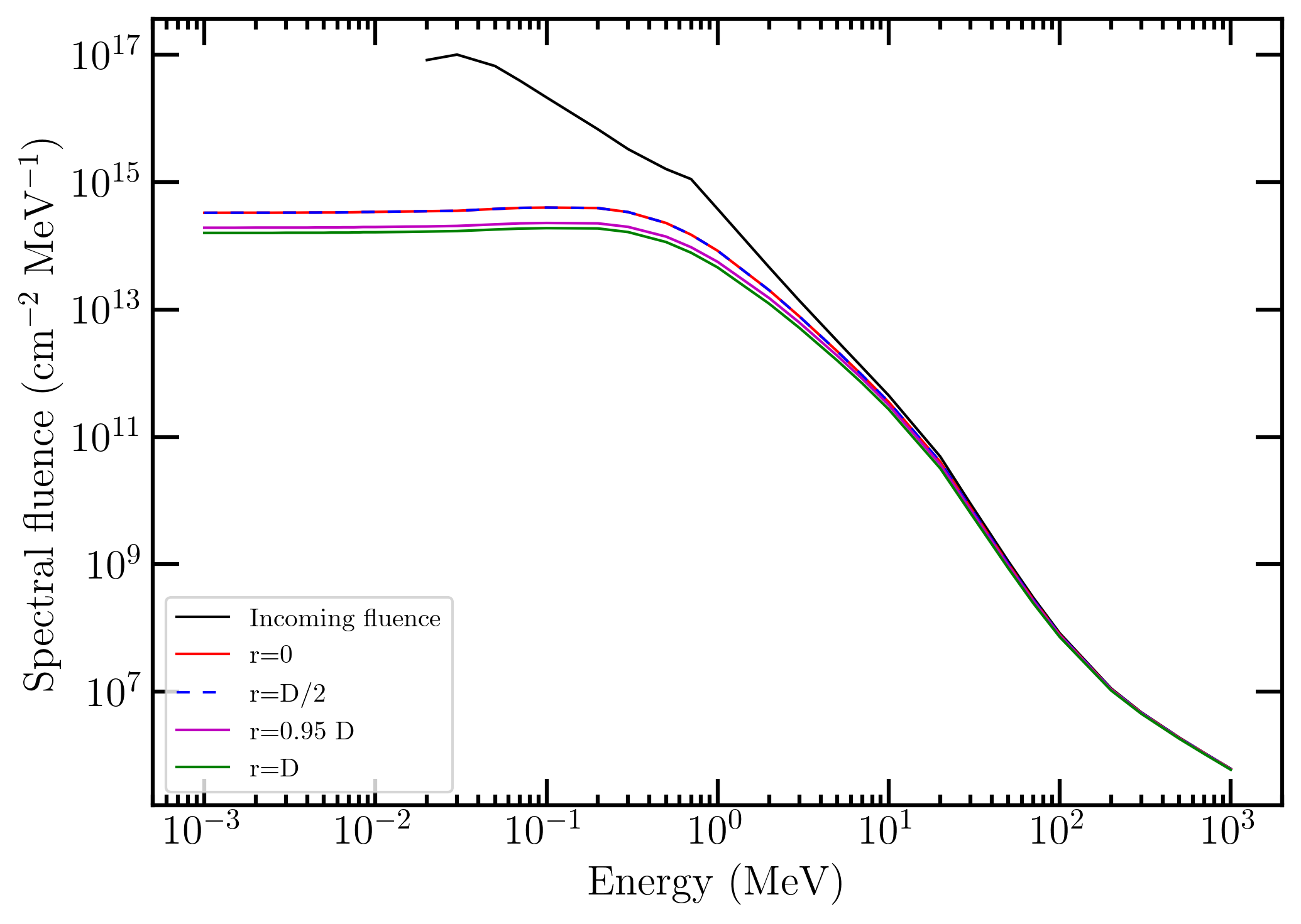
Incoming and residual spectral fluences as a function of r.
It has to be remarked that at r = 0 the residual spectral fluence is that obtained for a monodirectional spectral fluence impinging perpendicularly on a shielding material with thickness t. In fact, to rearch the sphere center, particles traverse the shielding material along radial directions thus resulting in traversed paths equal to the absorber thickness t.
In the following figure, the distribution of energies for 10 MeV of mono-energetic incoming electrons with a fluence of 100 particles cm-2 are shown for a) r = 0 all electrons have a residual energy of 9.3446 MeV (no plot is shown), b) r = D/2 , c) r = 0.95 D and d) r = D, where D = R - t where D = R - t with R = 50 cm, t= 0.127 cm of Al. The distribution were obtained assuming that particles traverse the shielding material with their flight direction unchanged.
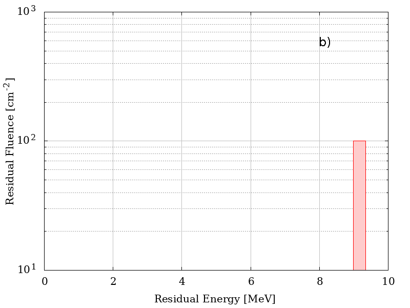
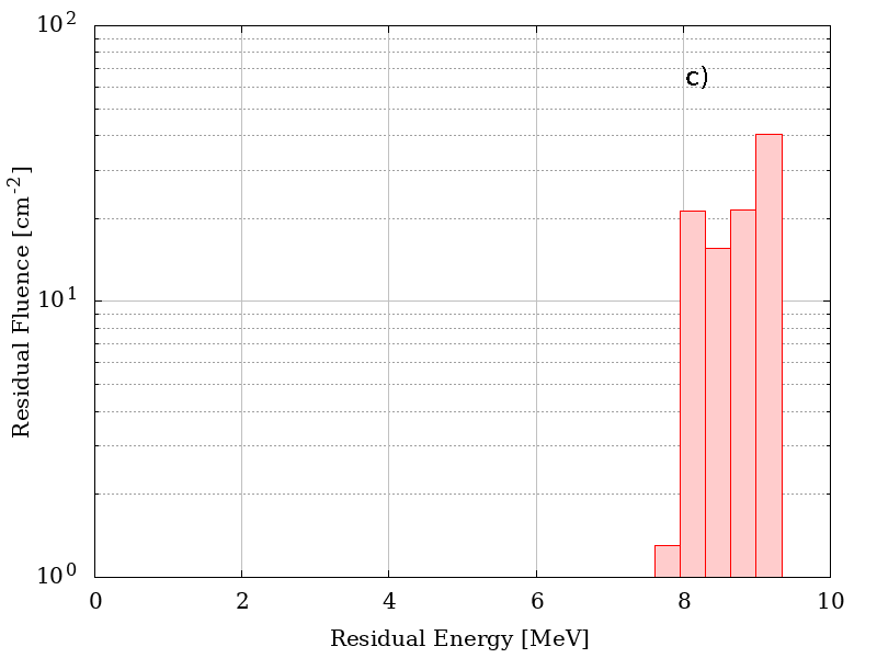
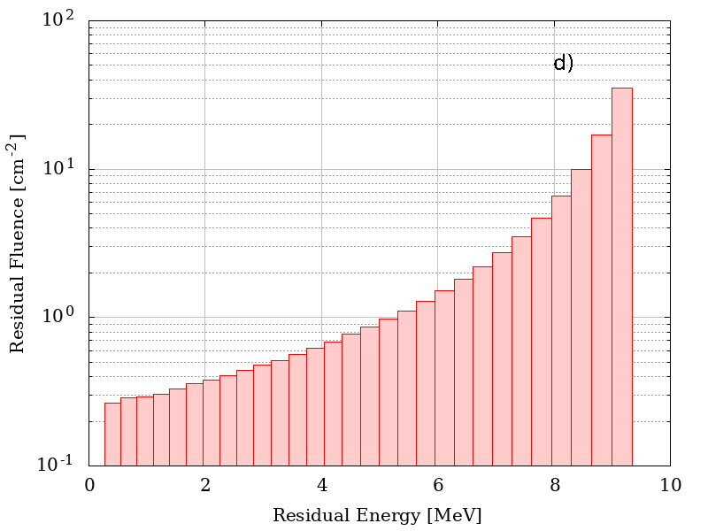
Residual energies as a functio of r.
Particle Spectral Fluence
This section define the points of the spectral fluence as a function of energy.
The input format is one point per line (Energy - Flux , separated by a space or tab); it is also possible to copy and paste values. The minimum value of the particle spectral fluence is 1 keV.
Mono-Energetic Particle
This section define the energy and fluence of the incoming protons or ions. The minimum value of the particle energy is 1 keV.
Result
In case of spectral fluence as input, the result page contains the graph of the input spectral fluence and the spectral fluence after traversing the absorber. The graph of the probability as a function of the traversed path is also provided. The table gives the values of the spectral fluence (above 1 keV) and the residual spectral fluence (above 1 keV) after traversing the absorber.
For mono-energetic particles the result page contains the graph of the distribution of energies after traversing the absorber. The graph of the probability as a function of the traversed path is also provided. The table gives the values of the residual fluence (above 1 keV) and the residual spectral fluence (above 1 keV) after traversing the absorber for each bin generated accordingly to the distribution of the probability as a function of the traversed path.
Residual energies were obtained disregarding multiple scattering effect, i.e., directions of flight of emerging particles were unchaged with respect to those of impinging directions.