

In the following, it is introduced how the electronic stopping power up to high energies and the restricted energy-loss - to account for the energy deposited in the medium or in a device - are treated within SR (Screened Relativistic)-framework.
The text is organized in sections:
The electronic stopping power in SR-framework
To a first approximation, at proton and ion energies large enough, the electronic stopping power is expected to be described by the energy-loss equation, i.e., Eq. (2.18) in Sect. 2.1.1 of [Leroy and Rancoita (2016)], where i) protons and ions (from He up to U) are considered almost fully-ionized, i.e., the square of the ratio of the effective charge state to the atomic number z of the incoming particle (ϖ2(β), e.g., see page 96 in [Leroy and Rancoita (2016)]) is equal or larger than 0.985 (see Figure 1) and ii) the term accounting for the non-participation of inner electrons of the medium (with atomic number Z) in the collision loss process is negligible (e.g., see Sect. 2.1.1.2 of [Leroy and Rancoita (2016)] and Figure 2).
ϖ2(β) is given by:
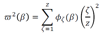 (1)
(1)
where ζ is the charge state of the ion and Φζ(β) is the fraction (function of β) of the time spent in that charge state.
At high energies, the density-effect term (e.g., see Eqs. (2.23-2.27) in Sect. 2.1.1.3 of [Leroy and Rancoita (2016)] and references therein) in the energy-loss equation takes into account that the range of distant collisions (e.g., Sect. 2.1.1 of [Leroy and Rancoita (2016)]) is extending and the atoms close to the particle path will produce a polarization, which results in the reduction the electric field strength acting on electrons at large distances, as pointed out by Fermi (1939) and others (for instance, see [Sternheimer (1961)] and Section 13.3 in [Jackson (1999)]). The parameters for the density-effect in a few media are reported in Table 1.
| medium |
I [eV] |
S0 |
S1 | a | md | δ0 |
| C | 78.0 | -0.035 | 2.486 | 0.202 | 3.004 | 0.10 |
| N | 82.0 | 1.738 | 4.132 | 0.154 | 3.213 | 0.00 |
| Si | 173.0 | 0.201 | 2.872 | 0.149 | 3.255 | 0.14 |
| Ga | 334.0 | 0.227 | 3.543 | 0.094 | 3.131 | 0.14 |
| As | 347.0 | 0.177 | 3.570 | 0.066 | 3.418 | 0.08 |
Table 1. The parameters, including the mean excitation energy I (in eV), for the density-effect in C, N, Si, Ga, As media from [Sternheimer, Berger and Seltzer (1984)] (see Table 1 and Table 2 in Sect. 2.1 of [Leroy and Rancoita (2016)] for the meaning of the parameters)
The ion charge state is treated in Sect. 2.2 of [Leroy and Rancoita (2016)] for z larger or equal to 2; at present, for protons it is commonly accepted that they do not have a bound electron at any velocity (e.g., see pages 74–79 of [Ziegler, Biersack and Littmark (1985)], Section 3.1 of [ICRUM (1993)] and Sect. 2.2 of [Leroy and Rancoita (2016)]).
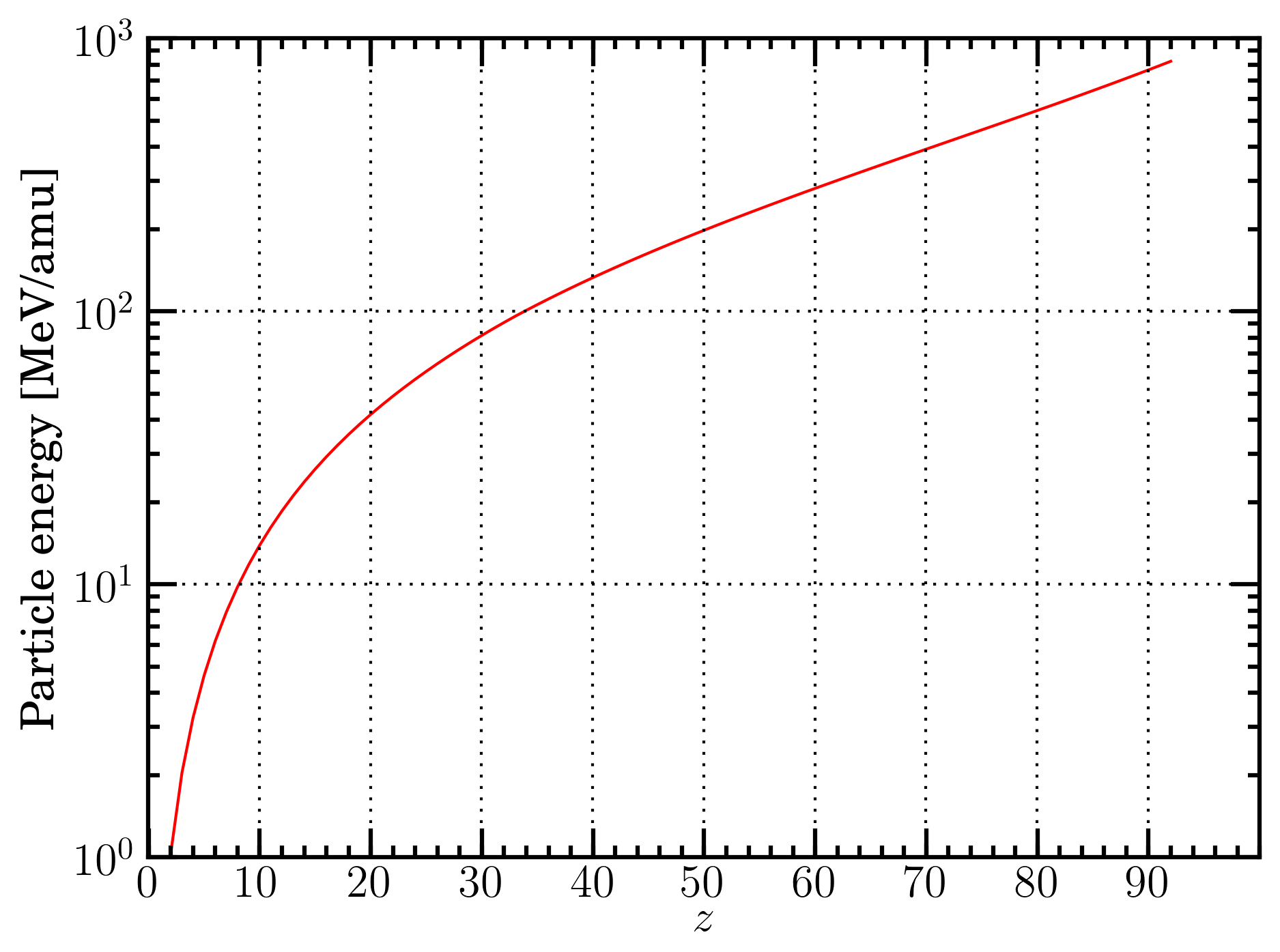 Figure 1. Energy in MeV/amu versus the ion atomic number z for ions from He up to U at which ϖ2(β) - see Eq. (1) - is equal or larger than 0.985: ion charge state is treated in Sect. 2.2 of [Leroy and Rancoita (2016)).
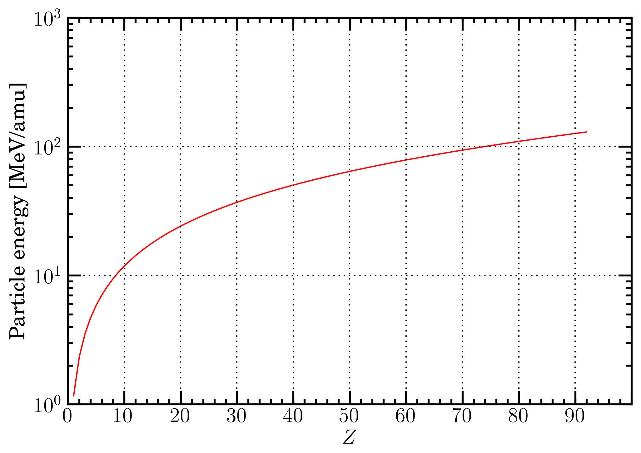 Figure 2. Proton energy in MeV/amu as a function of the atomic number Z of the medium at which the shell correction term is about 0.2 - e.g., see Sect. 2.1.1.2 of [Leroy and Rancoita (2016)] - in the energy-loss equation, i.e., Eq. (2.18) in Sect. 2.1.1 of [Leroy and Rancoita (2016)].
For completeness of information, it is shown a) in Figure 3, the charge state probability (Φζ) - computed using the equations at page 85 of [Northcliffe (1963)] and assuming that contributions from charge states lower than z-3 are negligible - as a function of the velocity in units of the Bohr orbital velocity of its own K-electron (ς0) divided by the ion atomic number z (see Sect. 2.2 of [Leroy and Rancoita (2016)]), b) in Figure 4, the ratio (ζ/z)2 as a function of the energy in MeV/amu for U-, W-, In-, Fe-, Si- and He-ions in a silicon medium and, finally, c) in Figure 6 ς0/z as a function of the energy in MeV/amu U-, W-, In-, Fe-, Si- and He-ions in a silicon medium. In Figure 5, the currently calculted charge state probabilities (Φζ) are compared with those originally derived and shown in Figure 3 right at page 84 in [Northcliffe (1963)]. Furthermore, in Table 2, the values of β, energy in MeV/amu and the corresponding maximum transferable energy (Wm in keV) to atomic electrons - during collision loss processes - at which the shell correction term is about 0.2 in the energy-loss equation, are reported for protons in a few materials.
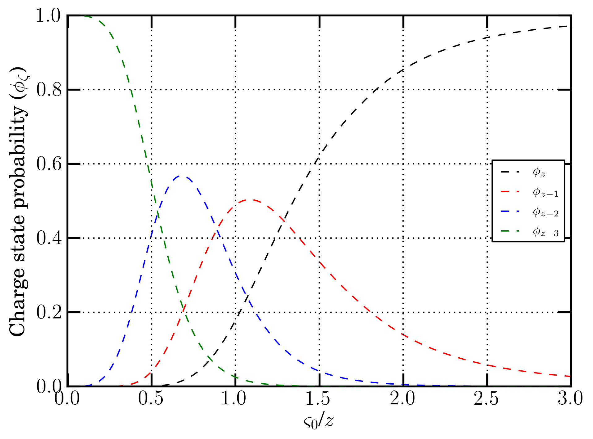 Figure 3. Charge state probability (Φζ) as a function of the velocity in units of the Bohr orbital velocity of its own K-electron (ς0) divided by the ion atomic number z (see Sect. 2.2 of [Leroy and Rancoita (2016)]). Curves are calculated from equations at page 85 of [Northcliffe (1963)]).
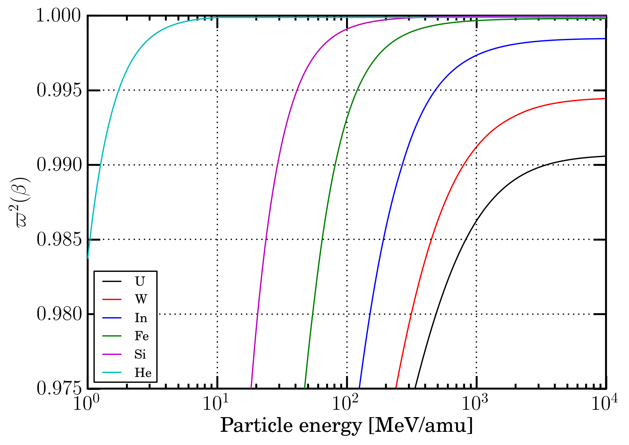 Figure 4. ϖ2(β) - see Eq. (1) - as a function of the energy in MeV/amu for U-, W-, In-, Fe-, Si- and He-ions in a silicon medium.
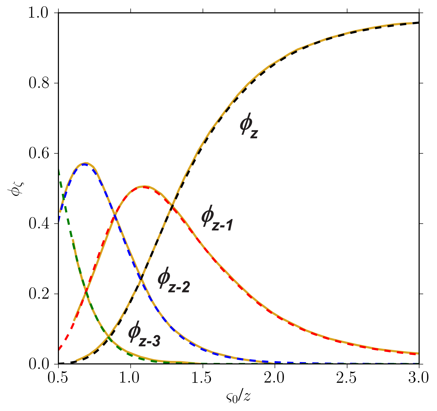 Figure 5. Currently calculated charge state probabilities (Φζ) (dashed curves) compared with those originally derived (gold solid curves) and shown in Figure 3 right at page 84 in [Northcliffe (1963)].
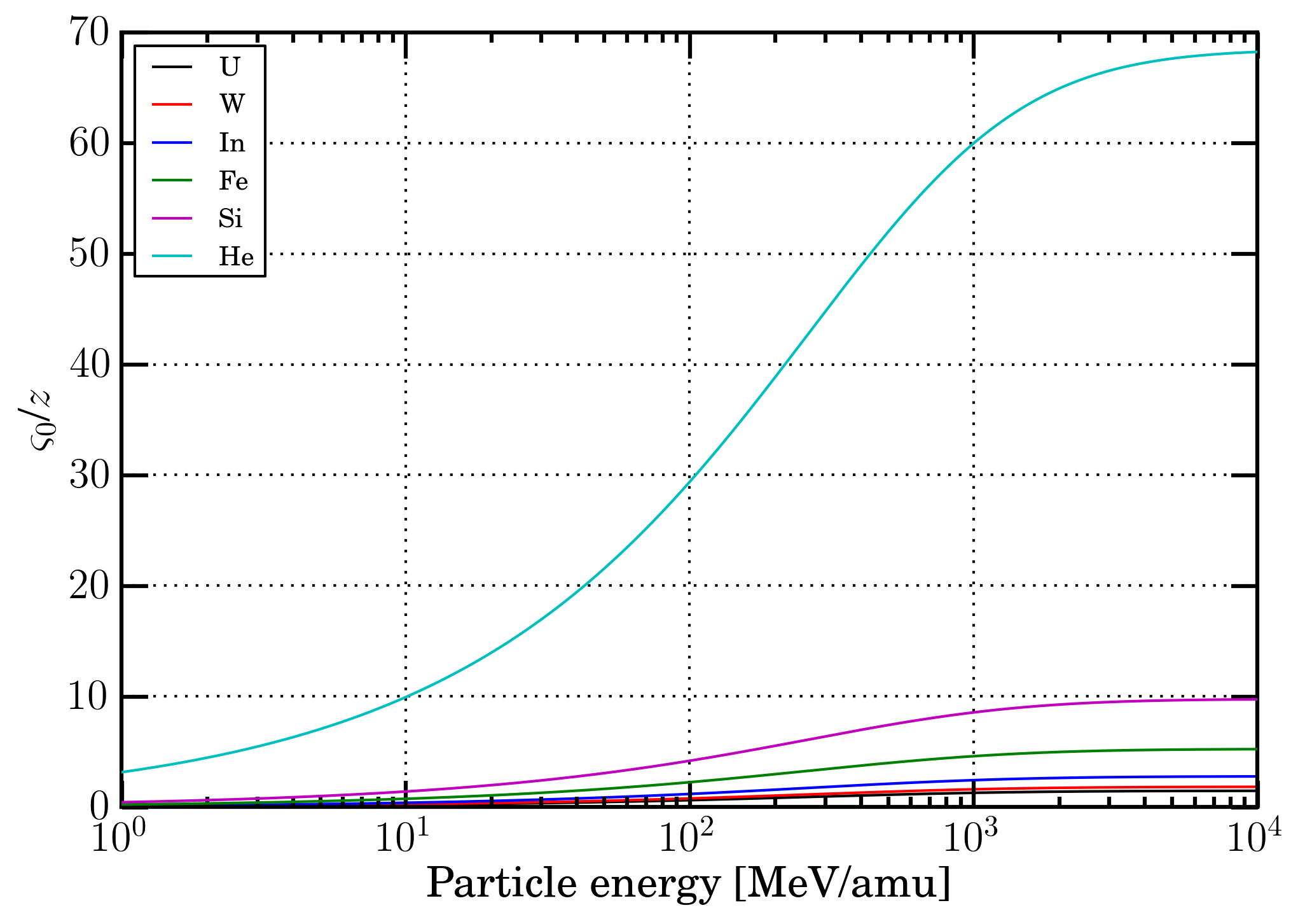 Figure 6. Velocity in units of the Bohr orbital velocity of its own K-electron (ς0) (see Sect. 2.2 of [Leroy and Rancoita (2016)]) divided by the ion atomic number as a function of the energy in MeV/amu for U-, W-, In-, Fe-, Si- and He-ions in a silicon medium.
| medium | β | E [MeV/amu] | Wm [keV] |
| C | 0.122 | 7.1 | 15.6 |
| N | 0.132 | 8.3 | 18.2 |
| Si | 0.187 | 16.7 | 37.1 |
| Ga | 0.278 | 38.3 | 85.9 |
| As | 0.287 | 41.0 | 91.9 |
Table 2. Values of β, energy in MeV/amu and the corresponding maximum transferable energy (Wm in keV) to atomic electrons - during collision loss processes - at which the shell correction term is about 0.2 in the energy-loss equation for protons in C, N, Si, Ga and As.
In the following the treatment will be quantitatively applied - as an example, to a silicon medium. i.e., to the most employed material for manufacturing microelectronic devices.
In Figure 7, the electronic stopping power from energy-loss equation of protons and ions in silicon are compared to those obtained from ICRU - protons and He-ions from [ICRUM (1993)], Si and Fe-ions from [ICRUM (2005)] - and SRIM; in Figure 8, the electronic stopping power from energy-loss equation of In-, W- and U-ions in silicon are compared to those obtained from SRIM (the electronic stopping power of these ions are not availble in [ICRUM (2005)]). The SRIM values used are those from SRIM 2013 code (SRIM Tutorials), i.e., they are those provided by SRIM code. In Table 2 the percentage variations of SRIM to SR-framework, ICRU to SR-framework and ICRU to SRIM regarding the data shown in Figures 7 and 8 are reported. By an inspection of Figures 7 and 8, one can remark that - see Table 3 - the energy-loss equation provides values for protons and He-ions in agreement within (or better than) 0.54% with respect to those from ICRU and SRIM, for Si-, Fe-, In-, W- and U-ions in agreement within (or better than) 2.97% with respect to those from SRIM; while the ICRU data differ from the ones from SRIM up to 7.21% (i.e., for Fe-ions).
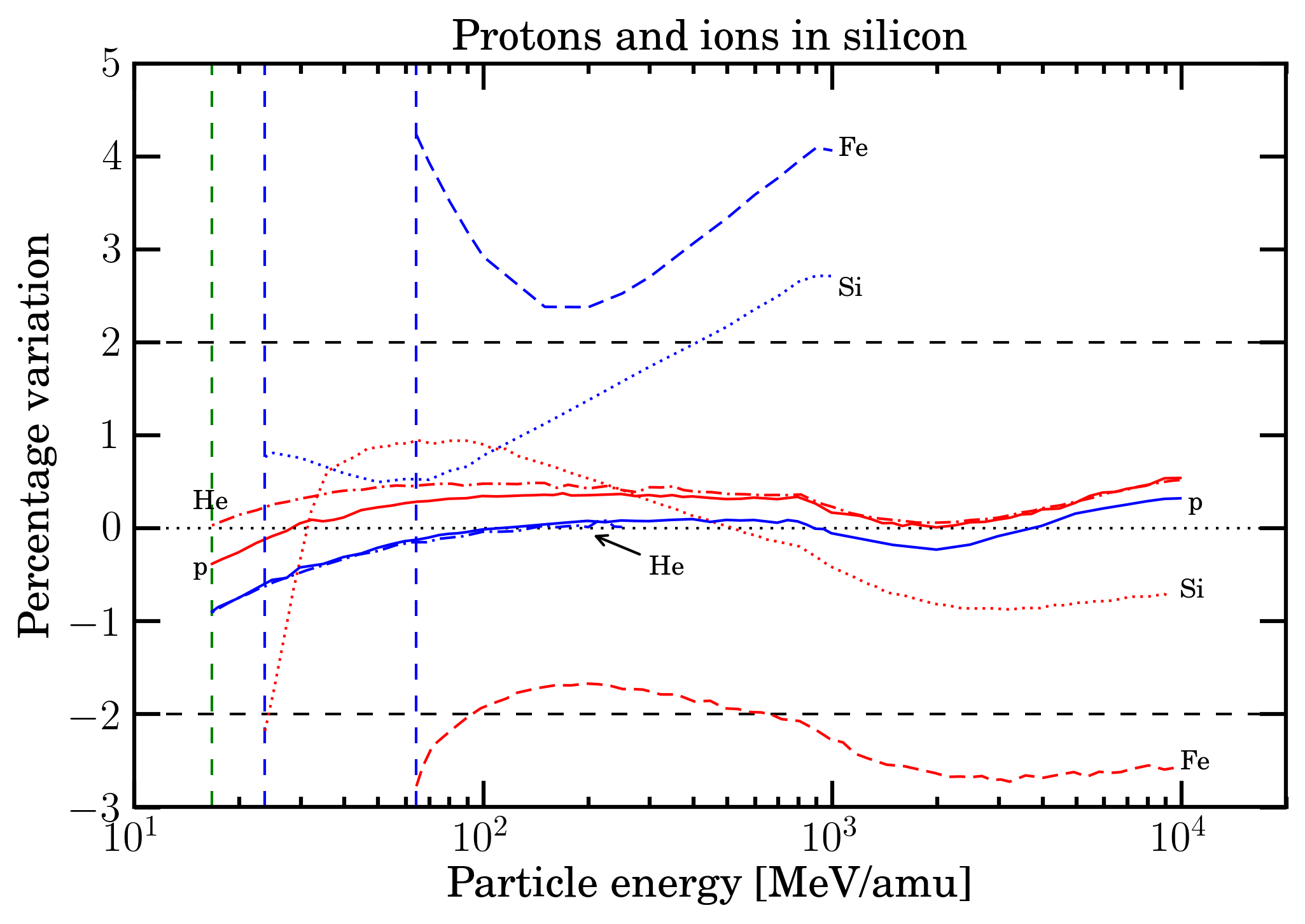 Figure 7. Percentage differences of SRIM (red curves) and ICRU (blue curves) - protons and He-ions from [ICRUM (1993)], Si and Fe-ions from [ICRUM (2005)] - data with respect to energy-loss equation (i.e., Eq. (2.18) in Sect. 2.1.1 of [Leroy and Rancoita (2016)]) for protons, He-, Si- and Fe-ions in silicon as function of incoming particle energy expressed in MeV/amu and up to the maximum energies available in SRIM and ICRU. The green dashed vertical line indicates the value of 16.7 MeV/amu at which, to a first approximation, the effects due to the non-participation of inner electrons of the medium in the collision loss process can be neglected (e.g., see Sect. 2.1.1.2 of [Leroy and Rancoita (2016)]). The blue dashed vertical line indicates the value of 23.7 (64.3) MeV/amu at which, to a first approximation, for Si (Fe) ions the energy-loss equation can be expressed neglecting the effects due to the non-participation of inner electrons of the medium in the collision loss process (e.g., see Sect. 2.1.1.2 of [Leroy and Rancoita (2016)) and the ion charge state is close to be that of a fully ionized atom (e.g., see Sect. 2.2 of [Leroy and Rancoita (2016)).
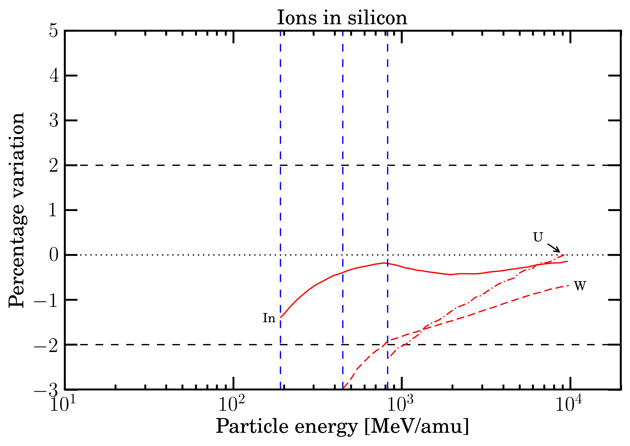 Figure 8. Percentage differences of SRIM (red curves) data with respect to those from energy-loss equation (i.e., Eq. (2.18) in Sect. 2.1.1 of [Leroy and Rancoita (2016)]) for In-, W- and U-ions in silicon as function of incoming particle energy expressed in MeV/amu and up to the maximum energies available in SRIM. The blue dashed vertical line indicates the value of 190.8 (447.2, 823.8) MeV/amu at which, to a first approximation, for In (W, U) ions the energy-loss equation can be expressed neglecting the effects due to the non-participation of inner electrons of the medium in the collision loss process (e.g., see Sect. 2.1.1.2 of [Leroy and Rancoita (2016)) and the ion charge state is close to be that of a fully ionized atom (e.g., see Sect. 2.2 of [Leroy and Rancoita (2016)).
| Particle | SRIM to SR-framework |
ICRU to SR-framework | ICRU to SRIM | |||
| From | Up to | From | Up to | From | Up to | |
| p | -0.38% | 0.54% | -0.90% | 0.32% | -0.52% | -0.12% |
| He | 0.03% | 0.52% | -0.90% | 0.08% | -0.93% | -0.37% |
| Si | -2.18% | 0.95% | 0.50% | 2.72% | -0.40% | 3.31% |
| Fe | -2.77% | 1.67% | 2.38% | 4.24% | 4.11% | 7.21% |
| In | -1.39% | -0.14% | ||||
| W | -2.97% | -0.68% | ||||
| U | -2.29% | 0.02% | ||||
Table 3. Percentage difference (from Figures 6 and 7) a) of ICRU and SRIM calculations with respect to Eq. (2.18) in Sect. 2.1.1 of [Leroy and Rancoita (2016)] and b) of ICRU with respect to SRIM values.
Within sr-framework, the electronic stopping powers are obtained using those from SRIM a) for protons at energies where the shell correction term cannot be neglected in the energy-loss equation, i.e., Eq. (2.18) in Sect. 2.1.1 of [Leroy and Rancoita (2016)] and b) for ions at energies where the shell correction term is no longer negligible and/or the ion charge state affects the scaling of the ion energy-loss with atomic number; for larger energies the energy-loss equation is employed.
The sr-framework treatment of electronic stopping power (previously discussed) allows one to extend its computation for particle energies (i.e., those accessible to energy-loss equation Eq. (2.18) from Sect. 2.1.1 of [Leroy and Rancoita (2016)]) large enough to fully deal with those corresponding to the current knowledge of cosmic rays spectra.
The restricted energy-loss in SR-framework
As discussed previously, since a device is usually not thick enough to fully absorb secondary δ-rays, the energy loss suffered by the incoming particle differs from the one deposited inside the traversed medium. As a consequence, the escaped δ-rays result in an effective detectable maximum transferred energy (indicated as W0 in the following) and, in turn, the deposited energy will reach a constant value, called the Fermi plateau at very high energy (for instance, in silicon for βγ > 744.7, i.e., protons with kinetic energies larger than about 698 GeV). Thus, when the energy deposited into a medium or a device has to considered, one has to deal with the so-called restricted energy loss - for instance, see the treatment by Fano (1963) - in which the effective detectable maximum transferred energy is accounted for (e.g., see Sect. 2.1.1.4 in [Leroy and Rancoita (2016)]). One has to remark that the physical mechanism of energy deposition per unit length in a medium (thus, the resulting computed value of restricted energy loss, see Eq. (2.29) and discussion at page 70 in Sect. 2.1.1.4 of [Leroy and Rancoita (2016)]) depends on the overall traversed path to which W0 is related. In fact, W0 value depends on absorber dimensions and on practical range of electrons in the medium; in addition, in Eq. (2.29) it has be great enough to consider the scattering occurring on a quasi-free electron of the medium, for instance, it has to be much larger than the mean excitation energy required.
In Figure 9, the practical range in g/cm2 of electrons is shown. The curve is obtained using Eq. (2.134) in Sect. 2.3.2 of [Leroy and Rancoita (2016)] (see also, Eq. (1-18) in Sect. 1-10 of [Price (1964)]). For electron energies where the radiation energy-loss is not a significant part of the energy-loss process, the practical ranges of electrons in units of g/cm2 are almost independent of the atomic mass-number of the traversed medium (e.g., see Equation (1-21) in Section 1-10 of [Price (1964)] and discussion in Sect. 2.3.2 of [Leroy and Rancoita (2016)]). Furthermore, values of the CSDA range of electrons in materials can be obtained from ESTAR database at NIST. Practical ranges and CSDA ranges of electrons may be employed to roughly estimate the values of W0 for microelectronic devices or semiconductor detectors.
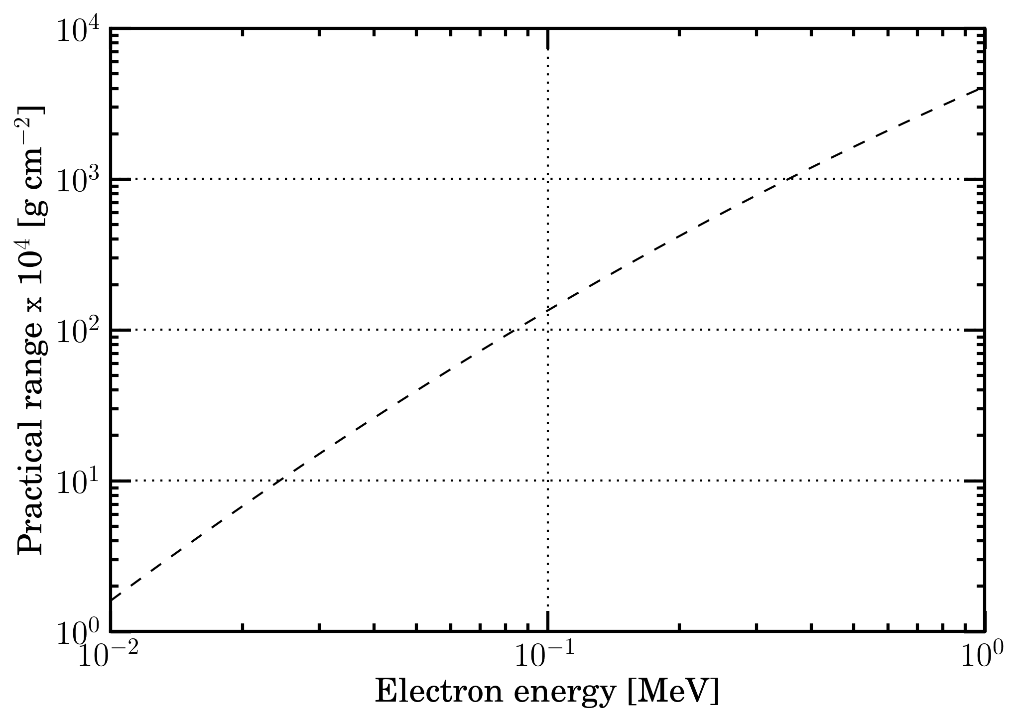 Figure 9. Practical range of electrons (see [Katz and Penfold (1952)], Eq. (1-18) in Sect. 1-10 of [Price (1964)] and Eq. (2.134) in Sect. 2.3.2 of [Leroy and Rancoita (2016)]) for electrons with energy from 10 keV up to 1 MeV. For electron energies where the radiation energy-loss is not a significant part of the energy-loss process, the practical ranges of electrons in units of g/cm2 are almost independent of the atomic mass-number of the absorber (e.g., see Equation (1-21) in Section 1-10 of [Price (1964)] and discussion in Sect. 2.3.2 of [Leroy and Rancoita (2016)]).
It has to be remarked - as discussed at page 70 of [Leroy and Rancoita (2016)] - that for all incoming particle energy for which the maximum transferred energy W (see Eq. (1.29) of [Leroy and Rancoita (2016)]) is lower than or equal to W0 there is no difference in between the SR-Framework electronic stopping power and the restricted energy loss (see Figure 10).
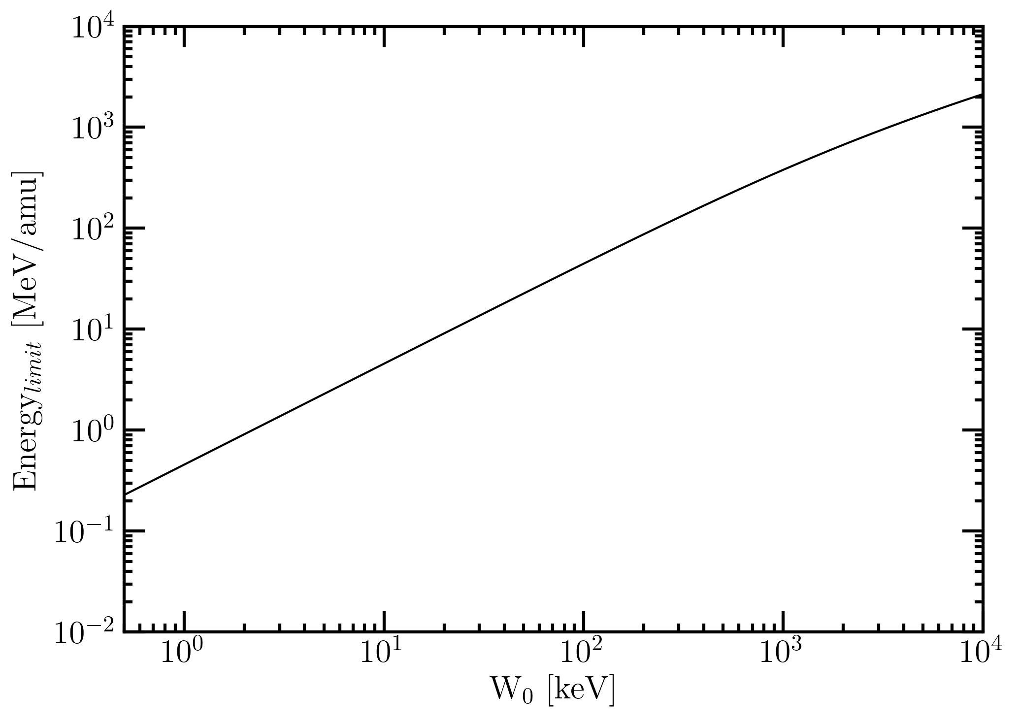 Figure 10. Energy limit (in MeV/amu) below which there is no difference in between the SR-Framework electronic stopping power and the restricted energy loss as a function of W0.
For instance, Esbensen et al. (1978) measured the energy deposition resulting from the mechanism of restricted energy loss using a 900 μm thick silicon detector and found a good agreement among experimental data and computed restricted energy-loss - from 690 MeV (βγ=1.41) - with the density-effect taken into account (see also [Rancoita (1984)] and here). The restricted energy loss from Esbensen et al. (1978) is shown in Figure 8 (9) of this webpage as a function of proton kinetic energy (βγ) and found in good agreement with the curve obtained - under the condition discussed in Sect. 2.1.1.4 of [Leroy and Rancoita (2016)] (e.g., see also Sects. 33.2.7 and 33.2.8 of [PDB (2018)]) - from the restricted energy loss formula (Eq. (2.29) in Sect. 2.1.1.4) from [Leroy and Rancoita (2016)] with W0 ≈ 0.5 MeV: at these energies the contribution due to the shell correction term can be neglected. One has to remark that restricted energy loss values for βγ > 100 (i.e., for protons with kinetic energies larger than 92.9 GeV) already approach that of the Fermi plateau within 0.5%.
By an inspection of both the energy-loss equation (2.18) in Sect. 2.1.1 of [Leroy and Rancoita (2016)] and the general energy-loss equation for ions at page 96 in Sect. 2.2 of [Leroy and Rancoita (2016)], it has to be remarked that:
- when the ion charge state is close to z (i.e., its atomic number), for protons and ions the restricted energy-loss as a function of the incoming particle energy can be directly computed using the above mentioned Eq. (2.30) in Sect. 2.1.1.4 from [Leroy and Rancoita (2016)];
- when the effects due to the ion charge state cannot be any longer neglected but the shell correction term can be neglected (i.e., see the above discussion on the energy-loss in the SR-framework), the restricted energy-losses as a function of the incoming particle energy can be obtained as a percentage difference from the actual electronic stopping power again using Eq. (2.30) in Sect. 2.1.1.4 from [Leroy and Rancoita (2016)].
However, in the latter case, the incoming particle energy must be high enough to allow one to disregard the contribution due to the shell correction term in energy-loss treatment (e.g., see the general energy-loss equation for ions at page 96 in in Sect. 2.2 of [Leroy and Rancoita (2016)]).
Finally, it has to be noted that the restricted energy-loss treatment is applied when the effective detectable maximum transferred energy W0 is smaller than Wm, i.e., the maximum transferable energy from the incident particle to atomic electrons. To a first approximation, when W0 is equal to or larger than Wm the energy lost by the incoming particle is deposited within the medium. Wm is discussed in Sect. 2.1.1 and Eqs. (1.29, 1.30) at page 15 of [Leroy and Rancoita (2016)]). The previously mentioned equations (1.29, 1.30) relate the maximum kinetic energy of the emitted atomic electron (assumed as a free electron at rest before the scattering) to the incoming particle energy.
As examples of their current implementation in the SR-framework, in Figures 11 and 12 (13 and 14), for protons (Fe-ions) in silicon the electronic stopping power and restricted energy loss and the ratio obtained from electronic stopping power divided by restricted energy loss are shown.
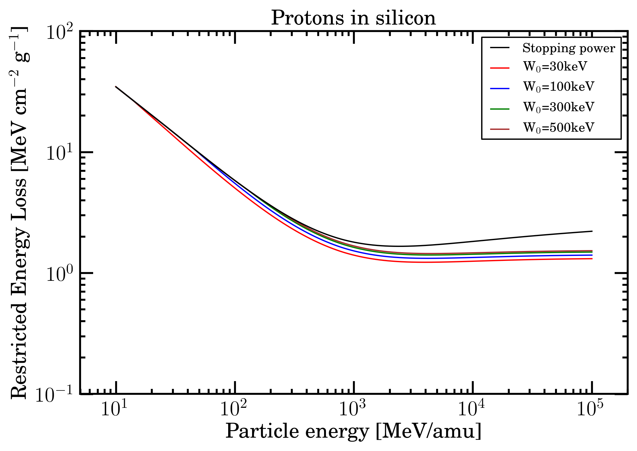 Figure 11. Electronic stopping power and restricted energy loss for protons in silicon (calculated for W0 = 30, 100, 300 and 500 keV) as a function of particle energy from 10 MeV/amu up to 100 GeV/amu.
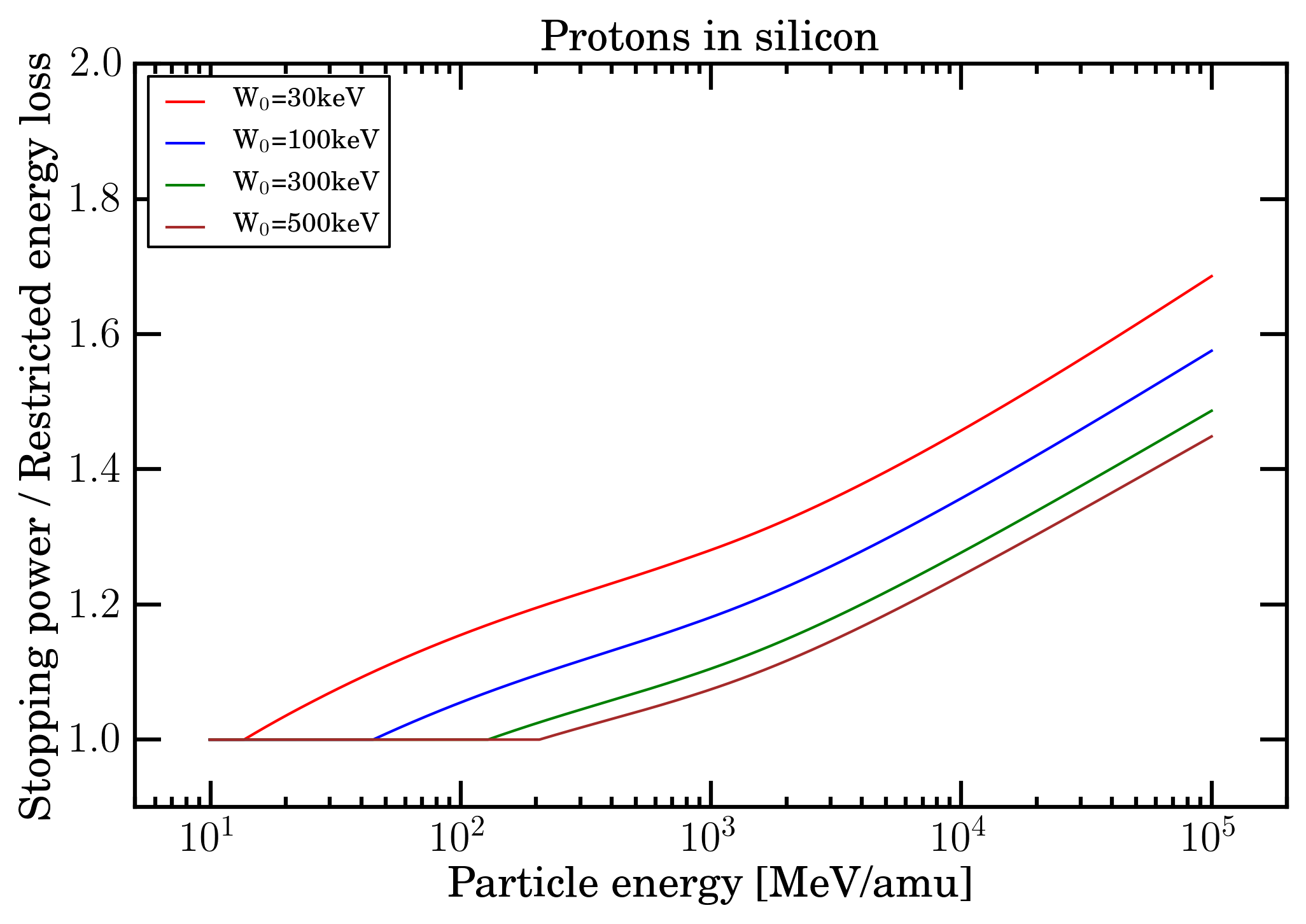 Figure 12. For protons in silicon, ratio of electronic stopping power divided by restricted energy loss (for W0 = 30, 100, 300 and 500 keV) as a function of particle energy from 10 MeV/amu up to 100 GeV/amu.
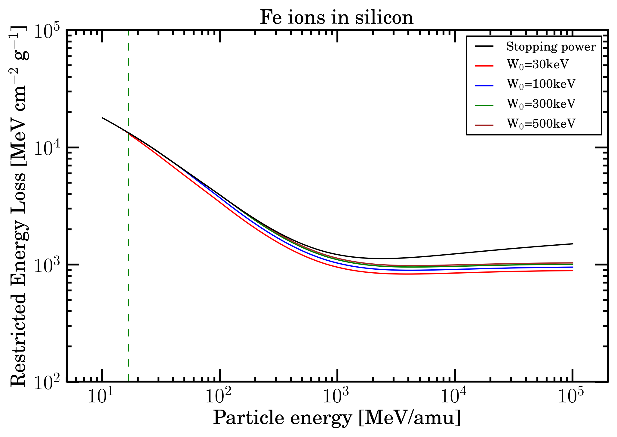
Figure 13. Electronic stopping power and restricted energy loss for Fe-ions in silicon (calculated for W0 = 30, 100, 300 and 500 keV) as a function of particle energy from 10 MeV/amu up to 100 GeV/amu. The green dashed vertical line indicates the value of 16.7 MeV/amu at which, to a first approximation the effects due to the non-participation of inner electrons of the medium in the collision loss process can be neglected (e.g., see Sect. 2.1.1.2 of [Leroy and Rancoita (2016)] and previous discussion).
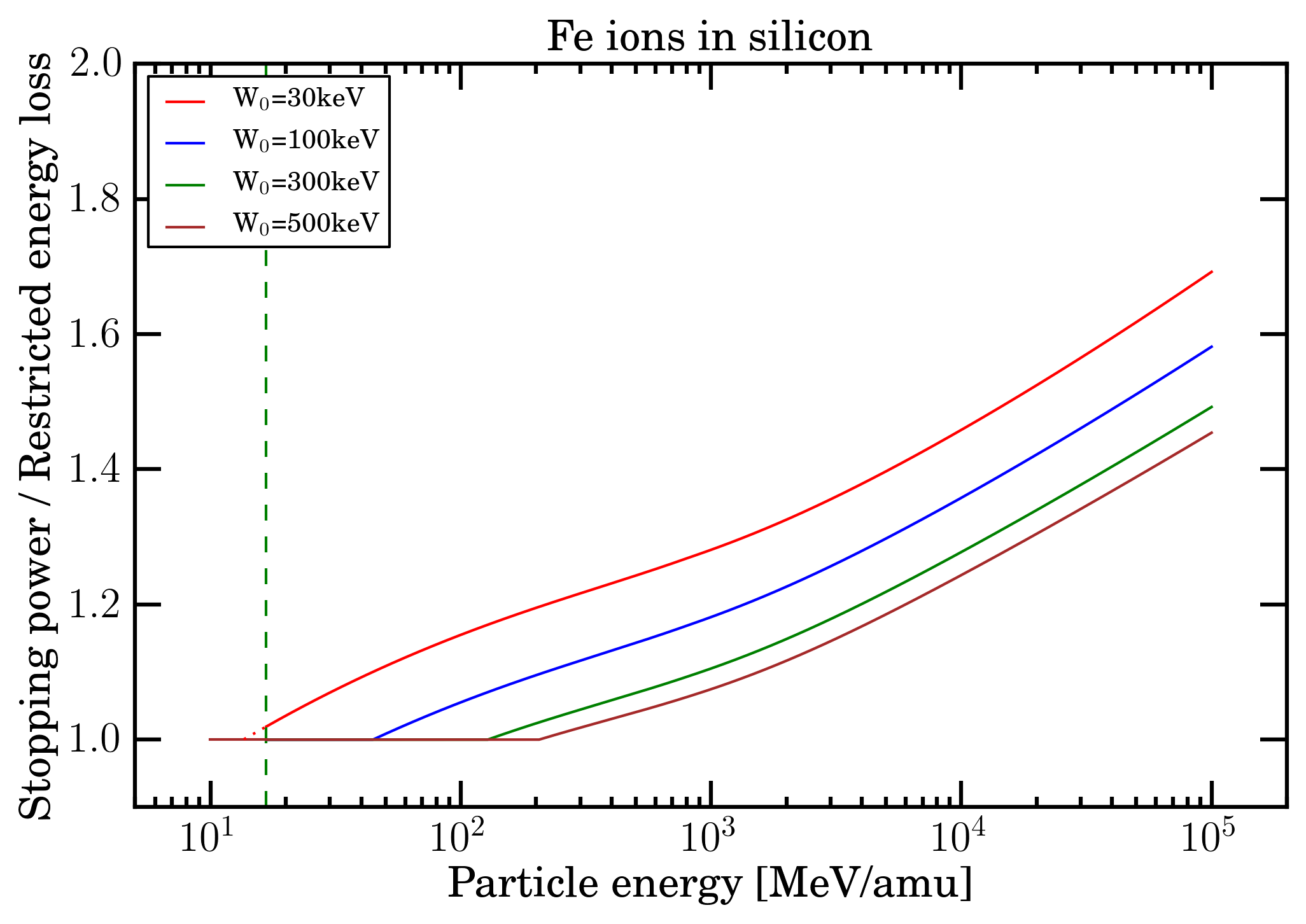 Figure 14. For Fe-ions in silicon, ratio of electronic stopping power divided by restricted energy loss (for W0 = 30, 100, 300 and 500 keV) as a function of particle energy from 10 MeV/amu up to 100 GeV/amu. The green dashed vertical line indicates the value of 16.7 MeV/amu at which, to a first approximation the effects due to the non-participation of inner electrons of the medium in the collision loss process can be neglected (e.g., see Sect. 2.1.1.2 of [Leroy and Rancoita (2016)] and previous discussion). For W0 = 30 keV, the restricted energy loss was interpolated (red dotted line) from 16.8 MeV/amu down to the energy of 11.9 MeV/amu at which one supposes that the energy lost by particles is fully locally deposited in the medium.
By an inspection of the mentioned figures, one can remark that the difference of the electronic stopping power increases (as expected) with the decrease of W0 values and, possibly, might be considered, for instance, in case of test beam measurements of microelectronics devices and/or semiconductor detectors. For instance, the value of W0 should account for the limited active depth of microelectronics components for particle impinging on the front side of the device and for the entire substrate thickness when particles enter at rear; while for fully depleted semiconductor detectors such an effect vanishes.
However, for cumulative (e.g., for ionizing doses) and non-cumulative (e.g., for SEE) effects in space applications the effective impact of replacing the electronic stopping power with the restricted energy loss has to be evaluated once it is combined with particle spectral fluences of SEP or cosmic rays. In particular for SEP protons, the usage of the restricted energy loss instead of the electronic stopping power is not expected to yield any appreciable difference, because the particle spectra are usually dominated by particle at energies below (10-20) MeV/amu.
Bibliography
[Esbensen et al. (1978)] Esbensen, H. et al. (1978). Phys. Rev. B 18, 1039.
[Fano (1963)] Fano, U. (1963). Ann. Rev. of Nucl. Scie. 13, 1.
[Fermi (1939] Fermi, E. (1939). Phys. Rev. 56, 1242 and Phys. Rev. 57, 485 (1940).
[ICRUM (1993)] ICRUM - International Commission on Radiation Units and Measurements (1993). Stopping Powers and Ranges for Protons and Alpha Particles, ICRU Report 49, Bethesda, MD; ICRUM (1993) values of electronic stopping power in silicon for protons and He-ions in silicon can are available from PSTAR website at NIST.
[ICRUM (2005)] ICRUM - International Commission on Radiation Units and Measurements (2005). Stopping of Ions Heavier than Helium, ICRU Report 73, J. of ICRU Vol. 5 No.1.
[Jackson (1999)] Jackson, J.D. (1999). Classical Electrodynamics - 3rd Edition -, John Wiley, New York.
[Katz and Penfold (1952)] Katz, L. and Penfold, A.S. (1952). Rev. Mod. Phys. 24, 28.
[Leroy and Rancoita (2016)] C. Leroy and P.G. Rancoita (2016), Principles of Radiation Interaction in Matter and Detection - 4th Edition -, World Scientific. Singapore, https://www.worldscientific.com/worldscibooks/10.1142/9167#t=aboutBook; ISBN-978-981-4603-18-8 (printed); ISBN.978-981-4603-19-5 (ebook); it is also partially accessible via google books.
[Northcliffe (1963)] Northcliffe, L.C. (1963). Ann. Rev. of Nucl. Sci. 13, 67.
[PDB (2018)] Tanabashi, M. et al. (Particle Data Group) (2018). Phys. Rev. D 98, 030001.
[Price (1964)] Price, W.J. (1964). Nuclear Radiation Detection - 2nd Edition -, McGraw-Hill Book Company, New York.
[Rancoita (1984)] Rancoita, P.G. (1984). Silicon detectors and elementary particle physics, J. Phys. G: Nucl.Phys. 10, 299–319, doi: 10.1088/0305-4616/10/3/007.
[Sternheimer (1961)] Sternheimer, R.M. (1961). Interaction of Radiation with Matter, Methods of Experimental Physics Vol. 5 part A, Yuan, L.C.L. and Wu, C.-S. Editors, Academic Press, New York, 1.
[Sternheimer, Berger and Seltzer (1984)] Sternheimer, R.M., Berger, M.J. and Seltzer, S.M. (1984). Atomic Data and Nucl. Data Tables 30, 261.
[Ziegler, Biersack, and Littmark (1985)]. Ziegler, J.F., Biersack, J.P. and Littmark, U. (1985). The Stopping Range of Ions in Solids, Vol. 1, Pergamon Press, New York.
Notes
[CSDA range] As discussed in ESTAR website, the CSDA (continuous slowing down approximation) range is a very close approximation to the average path length traveled by a charged particle as it slows down to rest, calculated in the continuous-slowing-down approximation (CSDA). In this approximation, the rate of energy loss at every point along the track is assumed to be equal to the total stopping power. Energy-loss fluctuations are neglected. The CSDA range is obtained by integrating the reciprocal of the total stopping power with respect to energy.
[practical ranges of electrons] In silicon, for instance, the practical range (from Figure 8) is about 6.5, 58.0, 335.6 and 703.9 μm for electrons with kinetic energies of 30, 100, 300 and 500 keV, respectively. Larger path length values are expected due to the scattering of electrons.